|

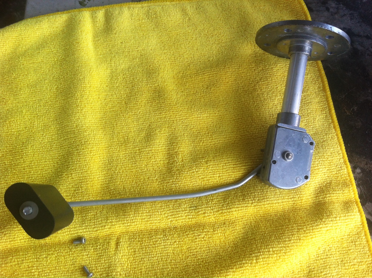
The above picture is the typical Beechcraft
fuel level sensor removed from the wing. Most Bonanza/Baron aircraft are
configured with an OUTER level sensor that deals with about the first half of
the tank and then an INNER sensor that deals with the second or bottom half of
the tank level.
IA and E55 Baron operator Stuart S. offers: Barons with
interconnected tanks, all model 58 and 1974 and newer model 55s have two 90 ohm
senders in the 'main' (40 gallon) tank and those with outboard leading edge
tanks 172 gallon capacity, an additional 19 ohm sender in that outboard tank.
The 30 gallon box tank does not have any senders.
Resistance increases with fuel quantity, but since the 19 ohm
sender is installed from the bottom of its tank the internal wiring is
different.
The same system was placed into the Bonanza around 1970 or so.
You can see why Model and SN are key when seeking fuel system gauge help.
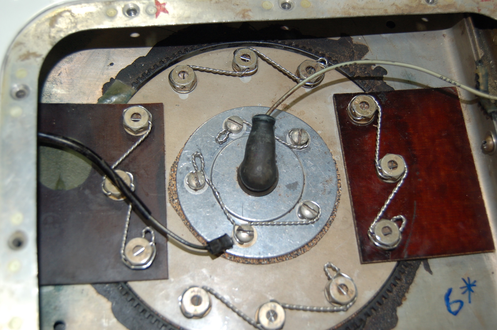
Below is a great example of excellent safety wire work by BT'er Tom N. on his fuel cell cover and sensor.
HERE is an
article by electrical and avionics guru John Collins, which describes the fuel
system sending units and their functions.
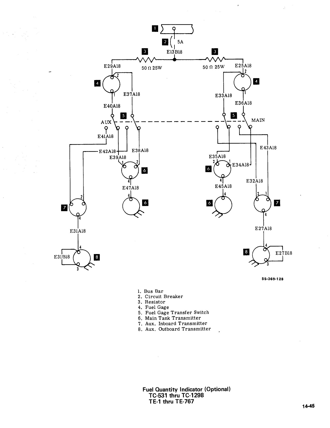
HERE is a
diagram of a range of SN: TC-531 thru TC-1298 for the B55 which uses the
separate MAIN and AUX tank configuration.
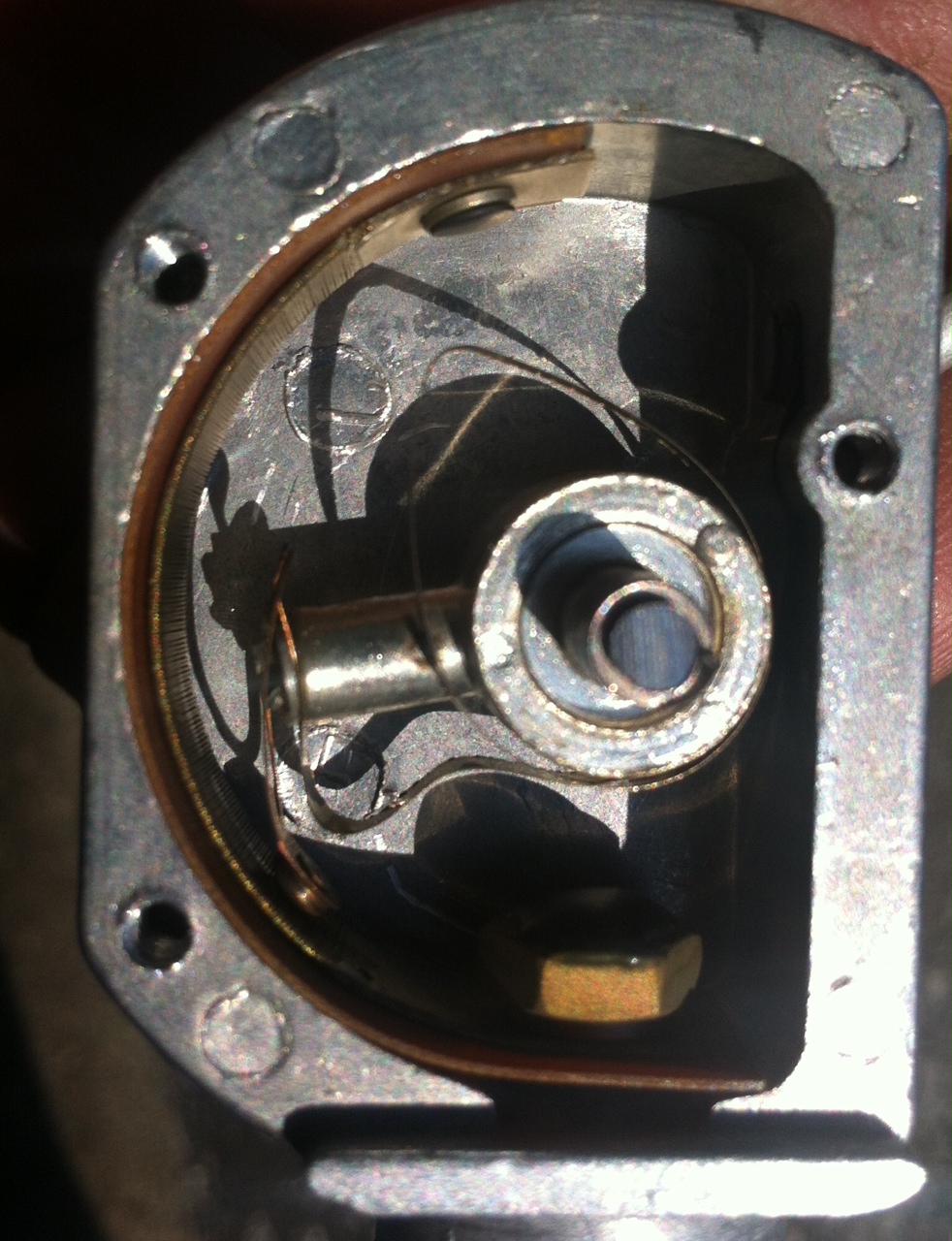
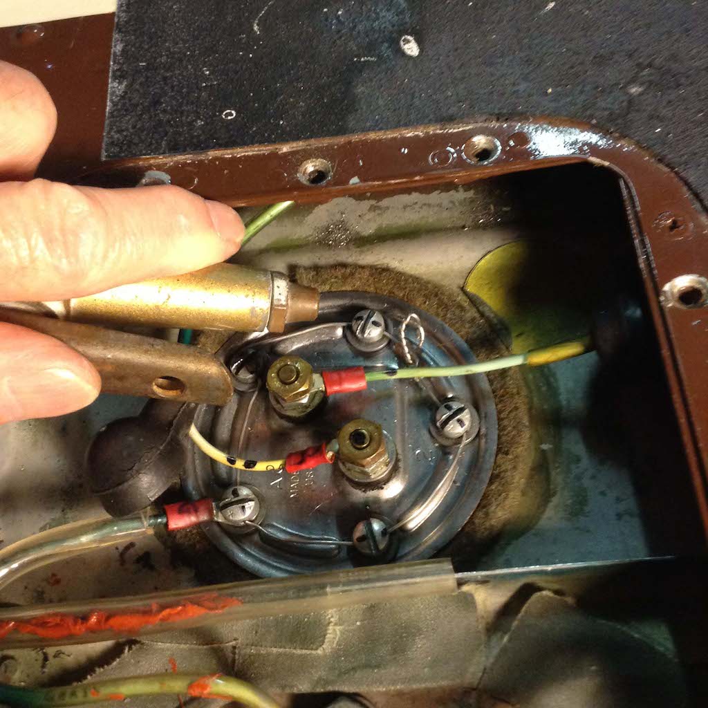
Here is what you will see when you open the
sensor up. It is nothing more than a wire wound resistor, like a rheostat that
is used to change the resistance in the circuit. The fuel gauges are essentially
voltmeters measuring the drop in voltage caused by the change in resistance as
the sensor moves up and down on the wire wound resistor element.
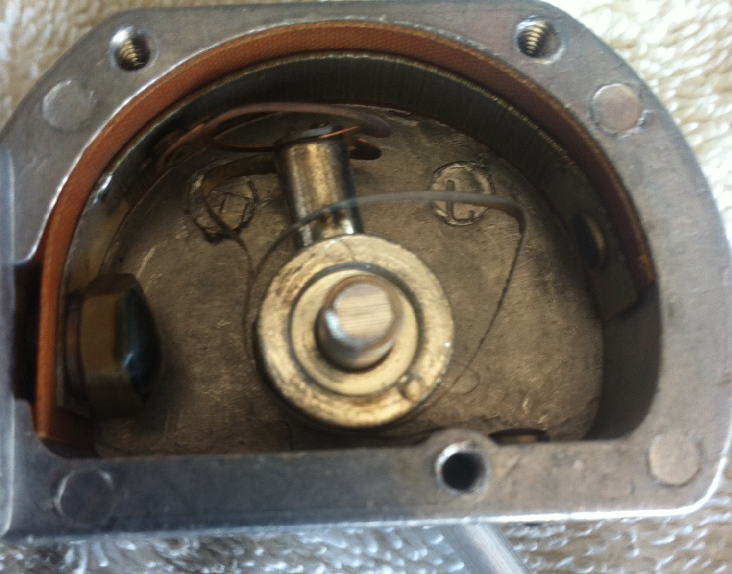
The problem creeps in when this wire wound
resistor develops corrosion or a break in the wiring. Many owners have found
good results in restoring accurate gauge readings by disassembling their sensors
and giving them a good cleaning with fine sandpaper and/or contact cleaner
solvent.
There is no seal on the sensor housing, it
functions immersed in the tank.
Since the resistor is
grounded, the resistance to ground is reduced by the
slider. There is always a constant path to ground so there is NO arcing.
There is play in the shaft to bushing
interface. Air containing dust and normal pollutants enters the tank through the
vents as fuel is displaced. These contaminants over the decades are believed to
cause the corrosion and coating of the wire wound resistor that results in
erratic or no readings at all from that particular sensor.
The fuel gauge system wiring varied greatly
over the years depending on SN. So please research the wiring diagram from your
shop manual for your particular serial number.
Do you have fuel gauge "modules" with
adjusting pots on the back of them? Suspect problems there? Check with Beech
Talker Hyland Lyle to rent or buy his "tester" for your gauges. His tester
instructions and contact info are
HERE
Hyland's tester is used on:
F33A E772 & up
V35B D10120 & up
A36TC EA1-EA272
F33C CJ149 &
up
A36 E1111-E2110
B36TC
EA273-EA319 EA321-EA388
See
Birks Aviation for
detailed info on the in cockpit fuel gauge "modules" and their replacement
modules.
Here is a picture of what an erratic fuel
gauge looks like in a 1949 Bonanza. Gee, I can't understand what was going
on....Can you see what could possibly be the problem?

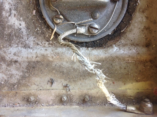
.
Clearly the ground cable is nearly severed and
the felt washer looks like it was just unearthed from King Tut's tomb. And check
out the safety wire job! Come on people, I know we can do better than this, and
the vast majority of Beech owners do, but Geez, this is embarasing! This is the
kind of thing that can cause an owner or casual operator of the aircraft to
believe they have fuel when in fact they don't. A fuel exhaustion "glider
rating" is somewhere in their future!

One can combat this kind of thing by liberal doses of Corrosion X or your
favorite anticorrosion spray on these connections in the sending unit at annual.
These connections send critical resistance measurements to the gauge which is
just displaying the reading it gets from the sending unit
Here is a narrative by Darrell S. on what he found when
he was looking for a leak emanating from the top of his fuel tank:
I developed a leak on the right side tank which I was
unable to find. The tank only leaked when it was full of gasoline. I took off
both inspection plates but could not see any blue stains.
I asked a local A&P to look at the tanks and he was
unable to locate the leak. His suggestion was "don't fill it all the way."After
a few sleepless nights I had another mechanic pull off the inspection plates and
look for the leak. He was unable to find any residue that would pinpoint the
leak. The fuel was coming out by the jack point on the bottom of the wing. The
mechanic said the only way to be sure is to pull the bladder and test it.
We pulled the bladder plugged the nipples and filled
the bladder with air. We soaped the the tank and saw that it was leaking around
the inboard fuel transmitter (p/n 95-380012-5). A close look revealed that the
housing on the sending unit was warped.
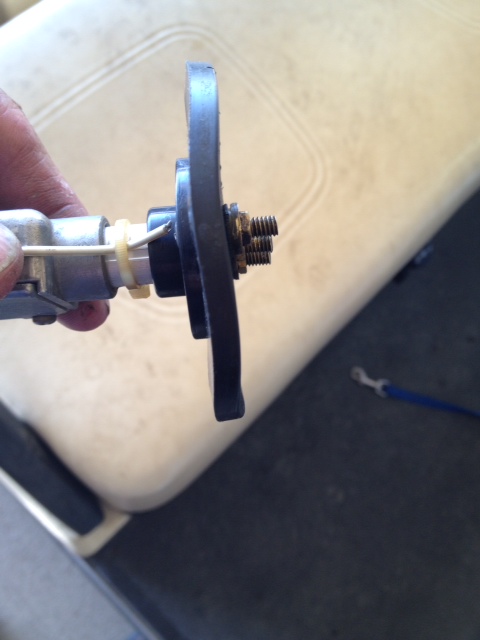
Above pictures courtesy of Beechcraft owner, David
T and Kevin O.
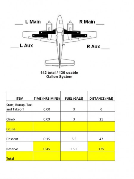
Below is a Fuel Chart for the Early 55-Series
airframes with separate Main and Aux tanks and 142 gallon system. Chart courtesy
of BT'er and Baron owner, Warren D.
Below is the Fuel System Diagram for 55 Series Barons SN: TC2003 and above with interconnected Main & Aux tanks
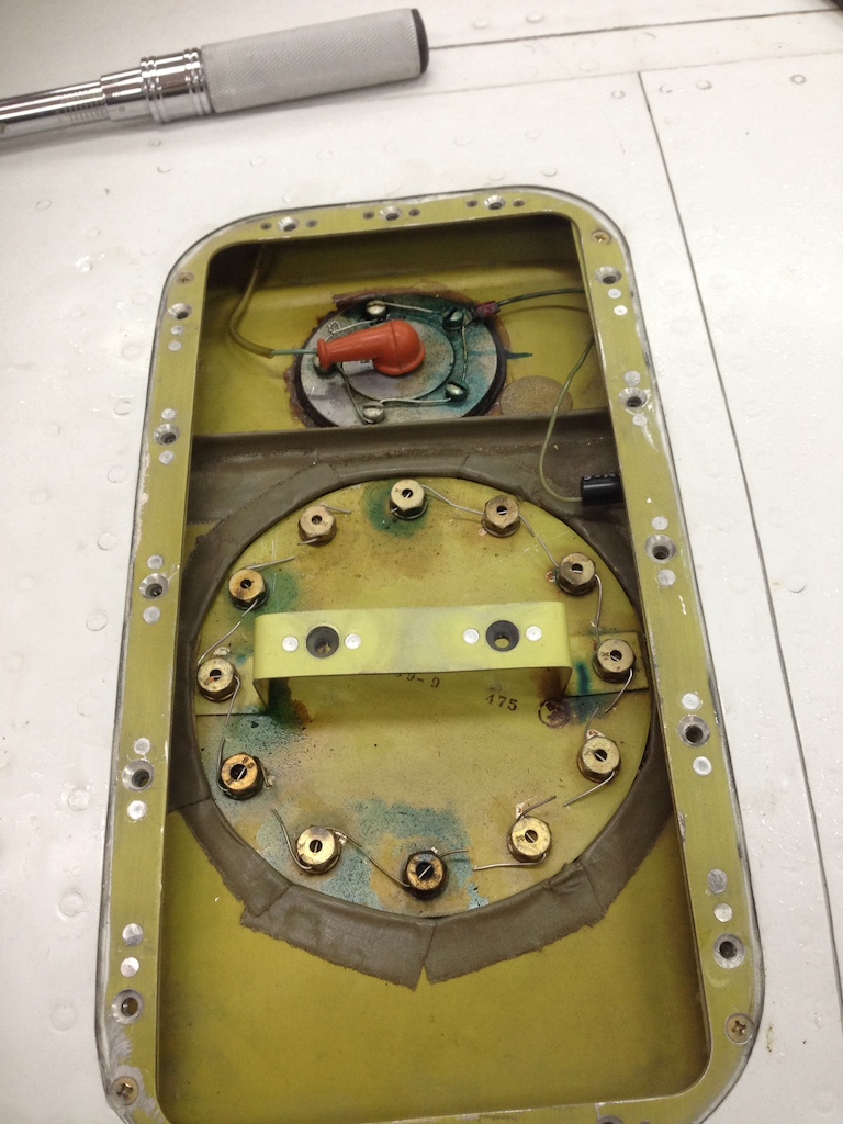
Below you will see pics of a leaking fuel tank
sending unit and inspection cover. Gaskets for these should be cork composition
and NO gasket sealer of any kind should be used on them. The best way to insure
proper sealing is to tighten them on Day #1 and come back on Day #2 and
re-tighten them, then apply safety wire.
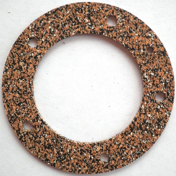
It is rumored that the 55/56/57 Chevy fuel
level sensor gasket was pressed into service by Beech for their sending units.
Available in many places for ~$10 or so plus shipping. Check out Amazon that
has them
HERE. This theory makes sense to me, since
their fuel level sending units seem to have been selected from the automotive
designs of the day.
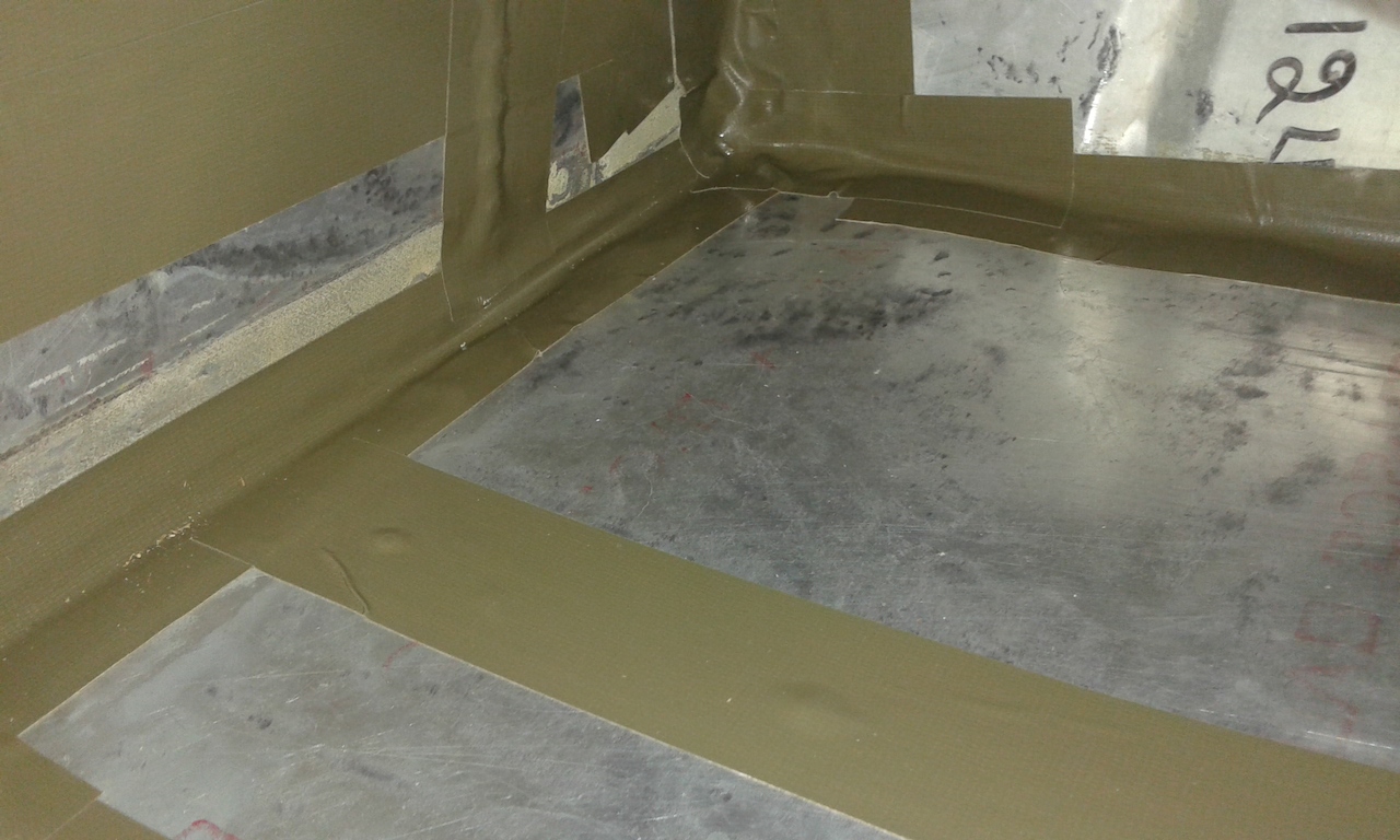
In case you decide you want to tackle a fuel
bladder replacement, this is the kind of taping job you need to be prepared to
deliver for the new tank to live in. More importantly, removing all the
liquefied adhesive that is all over the cavity.
So You Think You Want To Change A
Fuel Bladder? Click for Article
Consider these Sleeves if You're Diving into a Fuel Bladder R&R

Here's a way that Dr. Dave Rogers, an
aerodynamics expert, has identified to determine if your sending unit screws or
gasket are leaking. Simply shoot compressed shop air parallel to the mounting
face and if the high pressure air pulls fuel you've identified your problem!
See the excellent ABS fuel gauge articles HERE and HERE.
See a few great sources of fuel gauge repairs
and overhauls HERE
|